Design

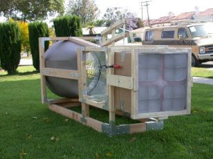
The following is an overview of the design of our wind tunnel. Though we knew generally what it would look like, we were unsure of how big to make it and in what proportions. One of the largest factors in this was, of course, the drive fan. We had a small diameter fan which we thought would work, but figured we'd try to find a larger, more powerful fan before resorting to using it - not that there's anything wrong with the small fan, but the more powerful, the better. After a bit of searching online, we contacted the Grainger company (see links) who offered to give us a 24 inch industrial fan which had a slight bend in part of the cage, preventing it from being sold. We picked up the fan on New Years' Eve 2001 with wide eyes as we realized just how big a 24 inch fan is.
So now we had a huge fan. What do we do with this thing? The answer was obvious: turn it upside down in Brett's garage and plug it in. That test told us that we were going to have one powerful wind tunnel.
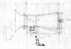
For 3 weeks the fan sat around as we got through the misery of semester 1 finals in school. On January 21 we actually got to work designing and building the thing. Our master plans are shown below. Drawn underneath the test section is an early design of the balance use to measure the forces acting on the test model and below that is a drawing of the principle of the balance. However, due to the complexities involved with the design, it was reworked into a much simpler and more effective balance.

721 x 497 [205kb]
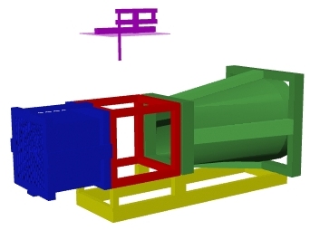
Something we realized early on, and something that has shown itself to be a good choice, is the construction of the wind tunnel in components. With something this size, a modular design makes it much easier to store and transport than a single large object. Here is an illustration showing how the wind tunnel is broken down:

Yellow: Stand
Blue: Air Straightener/Settling Chamber
Red: Test Section
Purple: Balance (raised)
Green: Diffuser/Fan
We decided to utilize a suckdown configuration for the tunnel (the fan pulls air through the tunnel rather than blowing through the tunnel) because of the turbulence problems that arise from air flow downwind of an axial fan. Originally we had planned to have a large contraction at the front of the tunnel, as shown in the plans, but in construction we decided to use no contraction at all because of the expense involved with an air straightener that large and the complex shapes needed in the tunnel walls. Ultimately we ended up with a straight section of tunnel forward of the test section containing the air straightener, 2 metal screens, and approximately 9 inches of open space for a settling chamber.
The air straightener was one of the major design hurdles we faced. We had no idea what we were going to use. We considered making interlocking panels of some sort to even out the flow, but didn't think we could do so neatly enough to not create turbulence of its own. Another choice we considered was using mailing tubes, but these seemed expensive for what they were. Weaker tubes would have worked, but we didn't have enough wrapping paper, toilet paper, and paper towel tubes sitting around to cover the area we needed and didn't feel like going out to find the amount we needed. So ultimately we came around to an idea we had run across earlier during design - using drinking straws. To cover the area of the opening (approximately 17" square) we bought 22 boxes of straws from Smart&Final, using about 20 full boxes. To contain the 5000 straws in the tunnel, we covered the front end of the settling chamber with a fine aluminum screen, tipped the chamber at an angle, and placed 16 boxes of straws into it, each box flap removed with the 4 sides holding in several hundred straws. The open areas between the boxes were then carefully stuffed with loose straws. This was, needless to say, a very careful operation and one which we got to try several times before having an acceptable air straightener.
When we were happy with this, we cut a piece of aluminum screen a little larger than the inside diameter of the tunnel with tabs at the corners, then pulled the tabs through holes cut in the side of the tunnel. The tabs were taped tightly to the outside of the tunnel and strong wires were pulled through the tunnel in an 'X' to help support the screen.
Testing of the tunnel with and without the air straightener shows just how effective it is. The smoothness of the wind is noticable just by placing your hand in the test section. At first we thought that the straws had cut down on the speed of the airflow because we couldn't feel the wind, but we soon realized that it was because the air was so smooth, there was so little turbulence that you couldn't feel the air disturbance against your hand.
The test section frame is built out of 2"x2" pine with metal brackets. The walls of the tunnel are plexiglass and all seams are sealed with smooth tape.
The diffuser contains the fan and molds the tunnel from the square profile of the test section into the circular fan. The frame is red oak, also joined with metal brackets, with the tunnel walls being heavy poster board, formed into the contour needed. The fan rests on one of the longitudinal members of the contraction frame which holds all its weight.
The entire tunnel rests on a red oak stand. Due most likely to humidity, the stand has pulled itself out of alignment, but the weight of the tunnel when in use generally holds the stand flat.
The wind tunnel balance is a simple dual beam design set up so that the mounting arm moves always moves perpendicular the air stream and the model is kept at a constant angle of attack. It is constructed of 1x2 inch pine with 1/4" brass bushings at pivot points. The shafts on which the pieces rotate are 7/32" brass tube. The model support arm itself is a piece of streamlined aluminum tubing; the model is mounted to it by a large clip made of 1/16" brass tubing that fits into holes in either side of the model. A counterweight is built into the opposite end of the arms to neutralize the weight of the model. See testing for more information.


